Posts

Showing posts from January, 2017

Distance on LCD display using Arduino and HC-SR04 Ultrasonic Sensor

Image
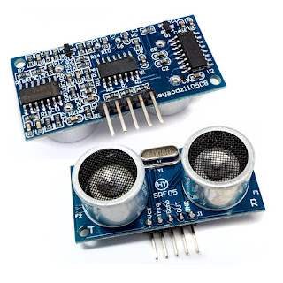
Distance On LCD   In this blog the distance measured by the Ultrasonic Sensor is Displayed on the LCD display using Arduino. Ultrasonic Sensor (HC-SR04) Ultrasonic ranging module HC - SR04 provides 2cm - 400cm non- contact measurement function, the ranging accuracy can reach to 3mm. The modules includes ultrasonic transmitter, receiver and control circuit.  The basic Principle of work: Using IO trigger for at least 10us high level signal. The Module automatically sends eight 40 kHz and detect whether there is a pulse signal back. IF the signal back, through high level, time of high output IO duration is the time from sending ultrasonic to returning. The total distance = (high level time x velocity of sound)/2 velocity of sound = 340 m/s Wire connections for the Module Complete circuit The module have 4 pins : VCC power supply Trigger Pulse Input Echo Pulse Output Ground 0V Connection with Arduino Connect Vcc to 5 V power supply from

LCD (Liquid Crystal Display) Arduino Interface

Image
LCD (Liquid Crystal Display) Arduino Interface   LCD (Liquid Crystal Display) screen is an electronic display module and find a wide range of applications. A 16x2 LCD display is very basic module and is very commonly used in various devices and circuits. These modules are preferred over seven segment and other multi segment LEDs. The reasons being: LCDs are economical; easily programmable; have no limitation of displaying special & even custom characters (unlike in seven segments), animations and so on. A  16x2 LCD  means it can display 16 characters per line and there are 2 such lines. In this LCD each character is displayed in 5x7 pixel matrix. This LCD has two registers, namely, Command and Data. The command register stores the command instructions given to the LCD. A command is an instruction given to LCD to do a predefined task like initializing it, clearing its screen, setting the cursor position, controlling display etc. The data register stores the data to

Black Line Follower .....

Image
Hi Friends today I'am Just providing you the code for the line tracer robot Below there are three codes for the Arduino. One for calibration Second for motor check and Third for the Line follower Upload the code of calibration and calibrate the sensors according to the readings on the serial monitor of Arduino software. Then Upload the code of the motor check and then check and check the working and orientation of the motors if not correct the you can correct it in two ways  First by changing the connections of motor  Second changing the code. I prefer for the change in code because it is easy and requires less time You can change the orientation by altering the pin no of the motor in the code. Finally make the changes of pin no if done so in second step in the line follower code and upload the code to the Arduino and you are done with it it........ For downloading the code click here. or for another link click here. For any quarry .... write in com