Efficently Reading Quadrature output on arduino
Efficiently Reading Quadrature With Interrupts
- Absolute position
- Incremental position
Absolute position encoders will tell you what the angular position is
all the time, even between power cycles. Most use "grey code" (a
modified form of binary) with several "tracks" (bits) to read position.
Incremental position encoders will tell you what the angular position
is, but only relative to where it was when you started paying attention
(usually on power-up). Two common types of incremental outputs are:
- Incremental (clever name)
- Quadrature
Incremental is rather useless for position control because it doesn't
give you any information about what direction you are turning, just that
you are turning. Quadrature encoders give you direction as well as
incremental position. This article deals with efficiently reading
quadrature output on an Arduino by utilizing external interrupts and
some AVR bare-bones code.
What is Quadrature?
How many magnets or slots are in a revolution of the encoder is known as pulses per revolution or p/r. Only the pulses on one channel are counted, the other channel will of necessity have the same number of pulses. Encoders can range anywhere from <10 p/r to 1000's of p/r, the higher numbers giving a higher resolution. If you are looking for maximum resolution, multiply the p/r by 4 since for each pulse there are two detectable events (rising edge and falling edge) on each channel. For example, a 1024 p/r encoder will give you 1024 pulses on channel A and 1024 pulses on channel B. If you detect both rising and falling edges on each channel, you have 4096 events in one revolution, giving an angular resolution of $$\frac{360^{\circ}}{1024 \tfrac{pulses}{rev} \times 4 \tfrac{events}{pulse}} = 0.0879^{\circ}/event$$
Selecting an Encoder
Selecting the best encoder for your design is more than just getting the highest resolution you can afford since the higher the p/r the faster you have to read the events. If you need to keep track of your position while spinning at 1,000 rpm with a 1024 p/r encoder, that means that between each event there is only
$$\frac{1}{1024 \tfrac{pulses}{rev} \times 4 \tfrac{events}{pulse} \times \frac{1000 \tfrac{rev}{min}}{60 \tfrac{sec}{min}} } = 0.000014648 sec \approx 15\mu s$$
You can see how a higher resolution than needed could result in not being able to keep up with the incoming information. Of course, if you needed to you could always just look for one edge on one channel and increase the 15 microseconds to 60 microseconds, but you loose resolution and direction when doing so.
From this example we can see some important factors that must be considered when selecting an appropriate encoder:
- What is your required angular resolution
- What is your maximum speed you need to be able to track
- How fast can you read and process the encoder output
The remainder of this article will deal with the third bullet point,
allowing you to read the encoder output as fast as possible. This will
give you more freedom when considering the other two points.
Too often I see people trying to connect the quadrature output to some digital inputs and read them in the program loop. The problem with this is that if your loop is slower than the incoming quadrature information, then you loose track of where you are. Wouldn't it be nice if there was a way to have the encoder tell us when it's ready to send information, rather than asking for updates every time around the loop?
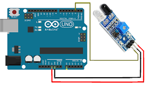
There is! It's called external interrupts, and an Arduino has two of them. Baically, you just connect the two quadrature output channels to the two interrups pins (digital pins 2 and 3 on a standard form factor arduino) and connect the interrupts in software:
Some important things here. First, I've defined enc_count as a global variable for future use. Next, an ISR (Interrupt Service Routine) is a bit of code that gets called whenever the interrupt is triggered. ISR's take no inputs and give no outputs (hence the need for a global enc_count). You'll define this bit of code yourself, and I'll cover that a bit later. Both interrupts (interrupts 0 and 1 on pins 2 and 3, respectively) are calling the same ISR. In general the can call different ISR's, but for our purposes we want them both to behave the same. Next, we see the word "CHANGE". This is telling the program to interrupt every time there is a change on the pin, whether it goes from low to high, or high to low. Other options in place of "CHANGE" are "FALLING", "RISING", and "LOW". Check out http://arduino.cc/en/Reference/AttachInterrupt for additional info on using interrupts.
So what happens is your loop is running happily along with no thought of checking the quadrature. Once one of the pins changes, the loop is interrupted, the ISR is executed, and once that's done the loop picks up where it left off. You must be careful to make the ISR as fast as possible, because your regular loop stops dead in it's tracks, and if you have any time sensitive stuff in the loop it may not work right. Also, you have to make sure the ISR ends before another one is called.
Connect Quadrature Output to External Interrupts
Too often I see people trying to connect the quadrature output to some digital inputs and read them in the program loop. The problem with this is that if your loop is slower than the incoming quadrature information, then you loose track of where you are. Wouldn't it be nice if there was a way to have the encoder tell us when it's ready to send information, rather than asking for updates every time around the loop?
There is! It's called external interrupts, and an Arduino has two of them. Baically, you just connect the two quadrature output channels to the two interrups pins (digital pins 2 and 3 on a standard form factor arduino) and connect the interrupts in software:
- volatile long enc_count = 0;
- void setup() {
- // all your normal setup code
- attachInterrupt(0,encoder_isr,CHANGE);
- attachInterrupt(1,encoder_isr,CHANGE);
- }
Some important things here. First, I've defined enc_count as a global variable for future use. Next, an ISR (Interrupt Service Routine) is a bit of code that gets called whenever the interrupt is triggered. ISR's take no inputs and give no outputs (hence the need for a global enc_count). You'll define this bit of code yourself, and I'll cover that a bit later. Both interrupts (interrupts 0 and 1 on pins 2 and 3, respectively) are calling the same ISR. In general the can call different ISR's, but for our purposes we want them both to behave the same. Next, we see the word "CHANGE". This is telling the program to interrupt every time there is a change on the pin, whether it goes from low to high, or high to low. Other options in place of "CHANGE" are "FALLING", "RISING", and "LOW". Check out http://arduino.cc/en/Reference/AttachInterrupt for additional info on using interrupts.
So what happens is your loop is running happily along with no thought of checking the quadrature. Once one of the pins changes, the loop is interrupted, the ISR is executed, and once that's done the loop picks up where it left off. You must be careful to make the ISR as fast as possible, because your regular loop stops dead in it's tracks, and if you have any time sensitive stuff in the loop it may not work right. Also, you have to make sure the ISR ends before another one is called.
The Look-up Table
I wish I could claim credit for what I'm about to share with you. But
the truth is, I can't. I found the concept in some dusty corner of the
internet. At the time I didn't understand what was going on, but through
copy and pasting code and some trial and error I was able to get it
working for the project I was working on at the time. Since then I have
figured out what was going on, and have expanded and generalized the
concept a fair amount. I went to find the website I originally got this
from, but was unable to locate it. If anybody has some idea of where it
came from, please post in the comments.
UPDATE: The source has been found! http://www.circuitsathome.com/mcu/reading-rotary-encoder-on-arduino
UPDATE: The source has been found! http://www.circuitsathome.com/mcu/reading-rotary-encoder-on-arduino
The idea here is simple enough: whenever there is a call to the ISR, the
previous levels of the channels is stored in memory and the new levels
are read. For convenience I will refer to the levels of the channels as xx
where the first number is the level of channel A and the second number
is the level of channel B. For example, progressing through states 1-4,
the channel levels are written as:
- 00
- 10
- 11
- 01
Imagine we were in state 1 and both channels were reading low, and then
the rising edge of channel A triggers an ISR and puts us into state 2.
The old reading of "00" is remembered for future reference and the new levels "10" are read. Let's concatenate these two pieces of information into "0010" for convenience. Progressing from state 2 to state 3, we are then left with "1011", where "10" is the levels the channels were at in state 2, and "11" is the levels the channels are at in state 3. Continuing through the remaining state changes, we go through "1101" and "0100"
to complete one period. There's nothing too tricky about any of this.
We're just listing the 4 numbers in each row of the table in the image.
If we were to continue to a state 5 and beyond, the strings of numbers
would then repeat.
We can go through a similar exercise in the reverse direction and get the following:
With a quick examination of the two tables we see that there are 8
unique strings of numbers, 4 describing clockwise rotation, and 4
describing counter-clockwise rotation. Now, all those rows look an awful
lot like binary numbers, so let's make it official and call them
binary. With 4 bits there are 16 unique numbers represented in binary
(2^4 = 16). So I'm just going to fill out a table with all 16 numbers,
and where ever there's a clockwise rotation I'll add a 1 in a new column, where ever there's a counter-clockwise rotation I'll add a -1, and everywhere else I'll add a 0.
By now maybe you see where this is going. It's quite elegant, really. If you don't see it yet, don't worry. I'll continue.
Typically, what I see done by others when reading quadrature is to check
a bunch of conditions and either add 1 or subtract 1 from the encoder
variable. What if instead we had a predefined array 16 entries long, and
the index of the array told us whether to add or subtract 1 from our
encoder variable?
- int8_t lookup_table[] = {0,-1,1,0,1,0,0,-1,-1,0,0,1,0,1,-1,0};
Seems simple enough, but how do we get which index we're looking for? If
you're not too familiar with how a compiler takes the program you write
and turns it into a program readable by a computer/microcontroller, it
might surprise you to hear that it doesn't matter one bit if you enter a
number in decimal or binary (or octal or hex), the end result will be
the same:
lookup_table[5] == lookup_table[0b0101]
So now, if we find a way to store the previous and current channel
levels as a binary number, we can use that information to index the
look-up table.
Binary Operators and PINs
I'll skip straight to the punchline here. The ISR that gets called whenever there's an event on either of the channels looks like this:
- void encoder_isr() {
- static int8_t lookup_table[] = {0,-1,1,0,1,0,0,-1,-1,0,0,1,0,1,-1,0};
- static uint8_t enc_val = 0;
- enc_val = enc_val << 2;
- enc_val = enc_val | ((PIND & 0b1100) >> 2)
- enc_count = enc_count + lookup_table[enc_val & 0b1111];
- }
This might look like a cryptic mess to you, but don't fret. It's not too difficult. Let's go through line by line.
Line 8 is just the ISR function. Remember that ISR's take no inputs and give no outputs..
Line 9 is the look-up table we worked out previously. The "static" in the front means that this is only set the first time the code is run, and it's remembered (and not reset) each subsequent time through the function.
Line 10 is for holding the binary number derived from the quadrature channels. We'll use this to index into the look-up table.
Line 12 is where we keep track of what the channels were last time around. the "<< 2" you see there says to shift the binary bits 2 places to the left. For example:
00110011 << 2 = 11001100
This is taking the 2 channel levels from last time and moving them left to match what's in our table images above. Whenever you shift bits, 0's will always fill in the new slots.
Line 13 is a little more complicated. You see a ">> 2" in there, you can probably guess it means take whatever is in "(PIND & 0b1100)" and shift it 2 places to the right. "PIND" is a very handy, very fast way of reading digital pins on an Arduino. Whenever the code comes across the "PIND" word, it takes the input readings on pins 0-7 and gives them as an 8-bit binary number with each bit representing a single pin. If pins 2, 4 and 7 are high, and all the others low, PIND would return "10010100". There are other PINs on an Arduino, and similar ways of writing to the pins and setting the pull-up resistors. I'll refer you to http://www.arduino.cc/en/Reference/PortManipulation for further reading on the subject.
The "& 0b1100" is what is sometimes referred to as a bit mask. When you use a single "&" like this (as opposed to the double "&&" in logical statements) it is a bit-wise AND, meaning each bit in the first number is ANDed with the corresponding bit in the second number to give an output. When reading the quadrature channels, we only care about the value on pins 2 and 3, but PIND is giving us 8 pins. So we apply a mask to ignore all the extraneous information:
10010100 PIND
& 00001100 MASK
----------
00000100 OUTPUT
The output only gets a "1" when both PIND and the mask have a "1" in that location, just like you would expect from an AND operation.
The last thing in line 6 is the "|". You're probably familiar with the OR logical operator "||". Just like the single "&", the single "|" works on a bit-wise level. So we are taking whatever is in enc_val and ORing it with everything to the left of it. Let's say enc_val contains the number 11001100, then:
11001100 | ((PIND & 1100) >> 2)
= 11001100 | ((10010100 & 00001100) >> 2)
= 11001100 | (00000100 >> 2)
= 11001100 | 00000001
So:
11001100
| 00000001
----------
11001101
After all that, what's left in enc_val is 11001101, where the "01" on the far right is the current levels of channels A and B, and the "11" just left of those is what the channel levels were the previous time through the ISR. the "1100" on the left is leftover information that isn't important to us any more.
Line 15 should be pretty straight forward after all that. You can see that there's another bit mask going on:
enc_val & 1111
= 11001101 & 00001111
So:
11001101
& 00001111
----------
00001101
The binary number 00001101 is equal to the decimal number 13, and is the index into the look-up table we've been after all along. To finish off, enc_count get's incremented by whatever value is in lookup_table[13], which is 1. Pretty nifty, eh?
Using Only 1 Interrupt
If you're using an arduino Mega, or the new Due, you have more external
interrupts to work with, so if you want to hook up multiple encoders or
you have interrupts dedicated to other hardware you're probably covered.
But if you're working on an Uno or one of it's predecessors, you are
limited to only 2 interrupts.
It is possible to use this same look-up technique with only 1 interrupt
per encoder. The trade off is that you will loose half of your
resolution. In this case, you would hook up the other channel to a
regular digital pin, and then rework your look-up table keeping in mind
that you can only detect when one of the channels is changing.
You might think I'm missing some information on the B channel, but
remember that the microcontroller only sees when A changes, and reads B
at that time. In the CW direction, when state 2 started A was high and B
was low. When it gets to state 3, A is low and B is high. We have no
information about when B changed from low to high, only that it is now
high. That's why we loose half the resolution when using only one
interrupt.
Working out the entire look-up table:
If you instead connected channel B to the interrupt, this table would be
different. One way to tell if you've done the table correctly is that
the direction column should always be symmetric about the middle. That
is, entry 1 should equal entry 16, entry 2 = entry 15, entry 3 = entry
14, etc. Meeting this condition doesn't guarantee that you've done it
right, but if you don't meet this condition I guarantee you've done it
wrong.
You will need to make some changes to the ISR as well. Line 6 in the ISR
above assumed that the quadrature channels were hooked up the pins 2
and 3. For convenience in the code, I suggest you keep the two channels
adjacent to each other whenever possible, i.e. pins 3 and 4 or pins 1
and 2. But remember the pins 0 and 1 are used for TX and RX.
If you connect channel A to the interrupt on pin 3, and channel B to pin 4, the ISR becomes:
- void encoder_isr() {
- static int8_t lookup_table[] = {0,0,0,-1,0,0,1,0,0,1,0,0,-1,0,0,0};
- static uint8_t enc_val = 0;
- enc_val = enc_val << 2;
- enc_val = enc_val | ((PIND & 0b11000) >> 3)
- enc_count = enc_count + lookup_table[enc_val & 0b1111];
- }
A Word on Debouncing
Usually with optical or hall effect encoders, there is no bouncing of
the channels that you need to worry about. But sometimes you want to use
an encoder as an input knob, and these encoders usually have mechanical
switches for the channels and are subject to bouncing. The proper way
to handle bounce (called debouncing) is to build a low-pass filter out
of a capacitor and resistor, and pass that through a schmitt trigger.
Some people like to deal with debouncing in software, but that adds a
lot of overhead to the code.
Using this look-up table method, you simultaneously eliminate most of
the ill effects of bouncing. In the event that either one of the
channels bounces, either you will switch back and forth between a +1 and
-1 and finally settle on the correct value, or you will come up with a
nonsensical combination of channel levels, in which case the look-up
table says to add 0 to the encoder counter. Magical!
Here's an example schematic of proper debouncing hardware. The encoder is in the middle with a schmitt trigger on each of channels A, B and the encoder button. There's 6 schmitt triggers in the 74HC14N IC, so you only need that one for up to two encoders with buttons.

sell used mobile phone in noida
ReplyDeletesell used mobile phone in khanpur